The air intake is the initial element of the mechanical ventilation system. It is the place where external, fresh air is drawn for ventilation or air conditioning devices. Air intakes are placed on the walls or roofs of buildings or are free-standing. In addition to drawing clean air, they protect the ventilation duct inlet from wind and precipitation. Want to know what affects the efficiency of the air intake? Here are some key factors...

Check the air intakes at the Onninen wholesaler
Choosing the right place to install the air intake
 Low efficiency of the air intake can result in unpleasant odours in the rooms, a decrease in the well-being of building users and a higher risk of allergies. The efficiency of the air intake (and the entire ventilation system) is significantly influenced by the place where the device is installed.
It is definitely a bad idea to place the air intake close to the air outlet (at a distance of less than 1.5 m), because it causes the risk of exhaust air flowing in – used air, which should be removed from the interior. The installation location must ensure efficient intake of fresh air and the coolest possible air in the summer season. Depending on the location, we can distinguish:
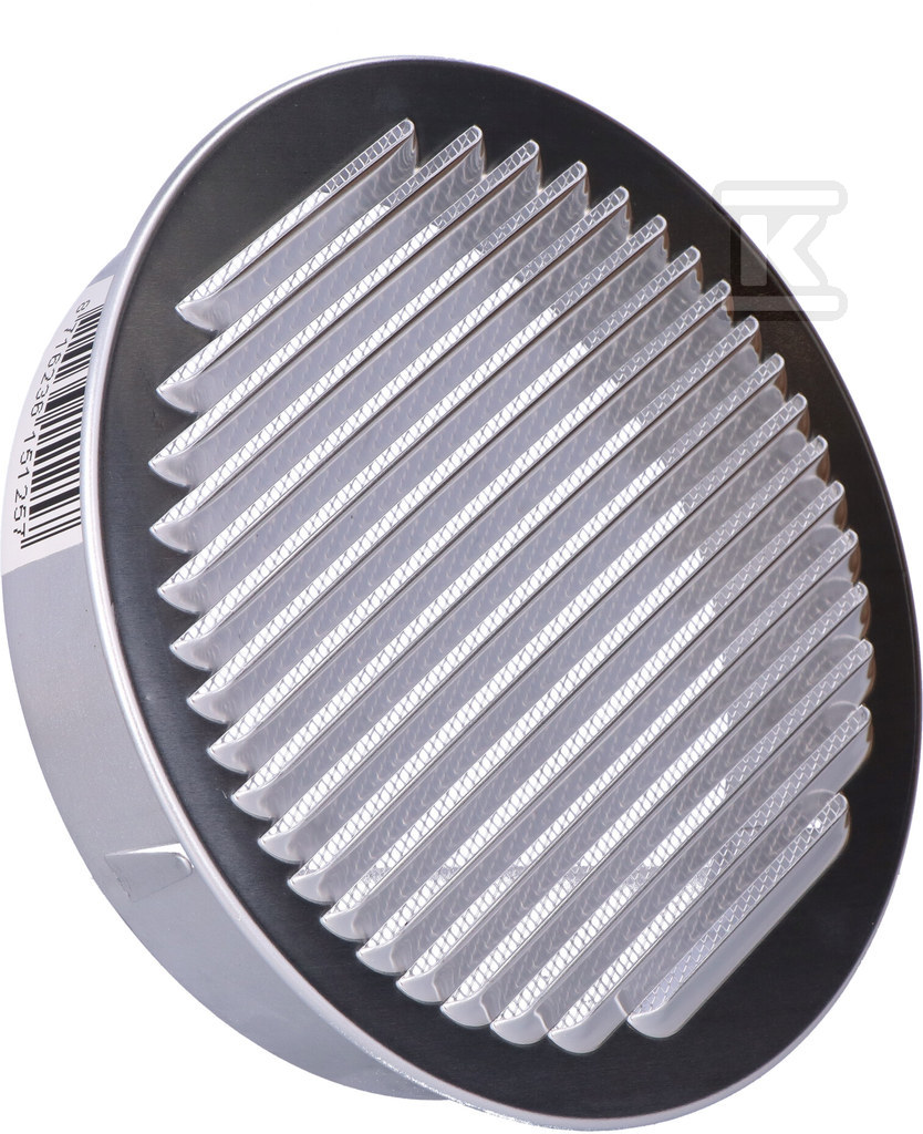
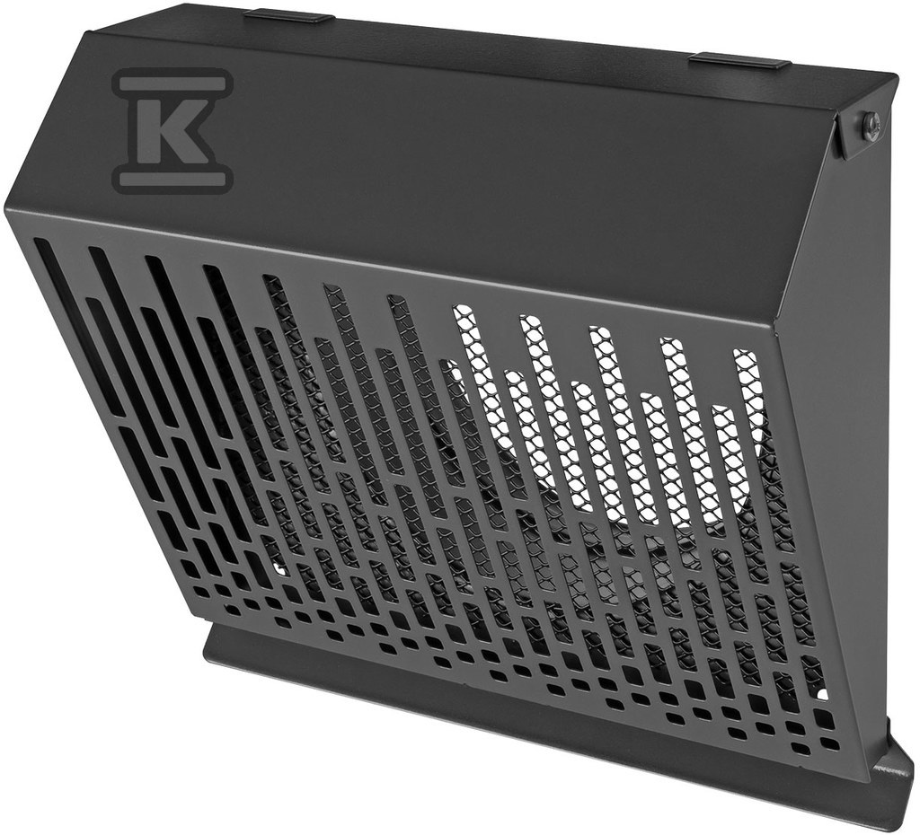
- wall air intakes - they are an element of the building's facade, most often they are rectangular or round in shape, and their opening is covered with slats and a protective mesh;
- roof air intakes - have a round or rectangular base, sometimes secured only with a mesh, allow for drawing fresh air from various sides (even four);
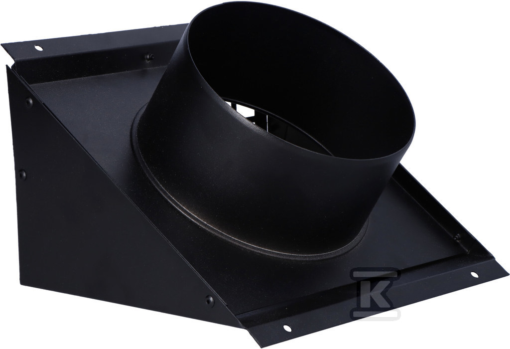
- field air intakes (freestanding) – installed next to buildings, usually they have a reinforced concrete or brick structure with a roof, sometimes the intake openings are equipped with equivalents of rectangular wall air intakes.
Regulations governing the installation location of the air intake
Detailed regulations governing the installation location of air intakes are included in § 152 of the Regulation of the Minister of Infrastructure on the technical requirements that buildings and their location should meet. First of all, air intakes in ventilation and air conditioning systems must be:
- protected against precipitation and wind;
- located in such a way as to enable collection of the cleanest and (in summer) coolest possible air;
- placed away from places with an increased risk of inflow of exhaust air from the exhaust vent and air with water spray from the cooling tower or other similar devices.
Rooftop air intake installation requires a distance of at least 6 m from sewage vents and at least 40 cm from the roof surface. Sidewall or ground installation requires a distance of at least 8 m from streets, parking lots, waste storage areas and other potential sources of air pollution.
The lower edge of the inlet opening should be at least 2 m from the ground level. Air intakes and exhausts must not be installed on roofs in explosion hazard zones. The regulations specify in detail the distances between these two devices. More restrictions regarding the installation location apply to exhausts (ventilation termination).
In practice, system designers have a big problem with determining the location of the intake that would fully meet the conditions described in the regulation. One of the biggest challenges is effectively securing the intake against precipitation and wind. This has been noticed by the manufacturers of intakes, who increasingly often provide structures that prevent water from entering the system. The effectiveness of water retention by the intake can be assessed using the PN-EN 13030 standard.
Recommended air flow rate through the intake vents
 It is worth knowing that the air flow speed through the duct has a significant impact on the pressure losses at the intake. A low air flow speed reduces the risk of water being sucked into the ventilation system and limits local pressure losses. The recommended air flow speed through the intake should range from 1 to 2.5 m/s. The following formula is used to quickly calculate the air speed:
v = Q/A [m/s]
Where:
- v – air flow velocity (m/s),
- Q – designed volume flow rate of air (m3/s),
- A – cross-sectional area of the channel (m2).
Maximum pressure loss at the intake
It is assumed that the maximum pressure loss at the air intake is from 20 to 40 Pa. As mentioned earlier, this value depends on the air flow speed through the air intake.
We encourage construction companies and stores, designers of air conditioning and ventilation systems, installers and service technicians to familiarize themselves with the assortment of our wholesaler. The category " Recuperation, air conditioning and ventilation " consists of thousands of products from leading brands in the HVAC industry. You will find everything that efficient and reliable ventilation and air conditioning needs. We offer, among others, ventilation fittings and ducts , air curtains, heaters and heating and ventilation devices, fans and insulation. Onninen consultants provide technical support.