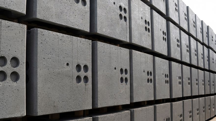
Cable wells are a product most often made of reinforced concrete. This facility of telecommunication sewage system or KT technological channel is used for pulling, connecting, branching or installing cable reserves and cable joints . There are several types of cable wells. These divisions result from the need to adapt the product to its intended use. Thus, we are talking about through, distribution, corner, building, under-cabinet or inspection wells. Details below!

From this article you will learn:
- what are cable wells used for,
- what are their types according to various division criteria,
- what requirements they should meet.
Let's start with what the purpose of cable wells is. Their basic function is to provide access to the remaining components of the cable duct system , i.e. pipes and cables. This access is necessary for network installation and maintenance or modernization. Additionally, thanks to the use of cable wells (e.g. from Styrobud ), it is possible to connect or branch cable supplies .
Division of cable wells in terms of application
- main chambers (SKM) - used for the construction of multi-hole cable ducts;
- pass-through cable chambers (SK) – intended for straight sewage sections, for example: SK-1, SK-2, SK-6;
- distribution wells (SKR) – used for branching cable routes or sewage bends, for example: SKR-1, SKR-2;
- corner cable wells – used at bends in cable routes;
- optimal cable chambers (SKO) - used both as through, corner or distribution chambers, the most universal group of chambers;
- through main chambers - used to build multi-hole (minimum 8-12 holes) cable ducts, mainly on straight sections of the duct system;
- main distribution wells - for multi-hole sewage systems (minimum 8-12 holes), when there is a need to branch or bend the sewage system.
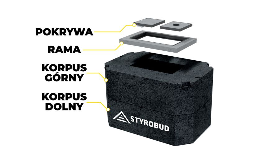 The base of the well is its body, which, depending on the model, may consist of one or even several elements. Additional equipment for a cable well may include:
- concrete settling tanks , used to drain water from the well chamber and provide space for the installer's legs;
- well holders and support tubes to support cables running through the well chamber;
- well finial , consisting of a frame and cover, serving as a hatch to the well;
- throats of cable wells , constituting a narrowing of the chamber of the well at the wall in which there are holes for introducing sewage pipes.
How to choose the right cable well?
At the stage of designing a new telecommunication sewage system, technological duct or fiber optic pipeline, when planning the selection of appropriate wells, we should first select the appropriate size and capacity of the well, taking into account the number of telecommunication sewage pipes . Most often, the name of the cable well immediately suggests how many primary sewage pipes (diameter 110) we can place in a given well. Therefore, it is crucial to select the appropriate well for the planned number of primary sewage pipes.
In the case of a single-hole sewage system, the following wells will be recommended: SK-1 as a through well, SKO-1 as a through or corner well with space for a sleeve, and SKR-1 as a branch (distribution) or corner well. For two-hole sewage systems, the following wells are recommended: SK-2 as a pass-through well, SKR-2 as a large distribution well or optimal SKO-2p/2g wells as universal wells. Their universality is based on a large number of entries in various places, giving the possibility of many applications , for example as passage elements, corner elements, distribution elements, building elements, etc. Three- and four-hole sewage systems require the use of SKO-4p (shallow) or SKO-4 (deep) wells. ). SK-6 (Warsaw type), SK-6 (2), SKO-6g and SKO-6p wells are recommended for six-hole sewage systems. Sewerage systems with eight to sixteen holes require the use of main pass-through cable chambers (SKMP-3), main distribution cable chambers (SKMR-3) or SKO-12, SKO-16 - as universal chambers. For sewage systems with sixteen to twenty-four holes, dedicated wells are SKMP-4 as a through hole and SKMR-4 as a distribution well. Larger sewage installations with 24 to 42 holes require the use of SKMP-6, and those with the number of holes in the range of 32-40 - SKMP-8 wells.
Other criteria for the division of cable wells
Types of wells can also be divided according to the number of body elements . According to this criterion, two types of wells are distinguished:
- single-element cable chambers - one-piece, monolithic body; a body made of one element (monolith) works well when at the construction stage there are no restrictions on the maximum weight of the well, i.e. we have heavy construction equipment; the advantage of this solution is the very quick and economical construction of a new cable duct;
- two-piece cable wells - two-piece body, consisting of a lower and an upper part; these wells are more popular due to their practical use - to build a given size (capacity) well, we do not have to rent heavy equipment (such as cranes) or a large excavator, because each time we lift a maximum of half the weight of the well.
 A well-designed and constructed cable duct/process duct should have good access to the pipe and cable system, which allows for the expansion, reconstruction and adaptation of the network . At the design stage, appropriate reserves and space for adding new cabling or possible expansion of fiber optic infrastructure should be taken into account. The sewage system should also be made of appropriate materials that will ensure tightness against sand and silt. Ideally, it would also be waterproof. The wells must be adapted to all types of cables used in telecommunications and protected against burglary. You should also remember to choose the size of the well so that after installing the entire installation there is still room for the installer, who should have easy and safe access to the cabling . Cable ducts made with these features in mind should allow for trouble-free use for many decades.
Terminology dictionary
- cable ducting , also known as telecommunications or telecommunications ducting - it is a sequence of protective pipes (usually fi 110) and cable wells, used for pulling/installing telecommunications cables, including optical fiber, copper, and pipe repeaters (e.g. fi 32), and micropipes;
- primary sewage system – a system of protective pipes and cable wells laid directly in the ground; the diameter of the pipes in 99% is 110; primary sewage pipes between wells should be arranged as straight as possible;
- secondary sewage – the so-called HDPE optocommunication pipes with diameters of Ø 32 or Ø 40, placed inside the primary sewage system;
- microducts - this is a system of micropipes with a diameter usually in the range of 7-14 mm, into which microcables with diameters of 2-7 mm are pulled or blown;
- KT technological channel - the KT basic profile should consist of at least one RO casing pipe (fi 110 or fi 125), three RS pipes (e.g. fi 40) and one bundle of WMR micropipes and cable wells enabling the installation (pulling or blowing in) of cables and fiber optic microcables;
- cable pipeline - this is a system of casing pipes laid directly in the ground with accompanying infrastructure (such as wells and tanks), most often based on HDPE 32 or HDPE 40 pipes; the design of the pipes (internal grooves, slip layer) favors blowing fiber optic cables over long distances (about 1-2 km); the basic difference from cable ducts is the diameter of the pipes and a much lower density of the accompanying infrastructure, i.e. cable wells and/or cable trays;
- cable well - a telecommunications duct or KT technological channel facility used for pulling, connecting, branching or installing cable reserves and cable joints; the cable well is most often made of reinforced concrete, less often of plastics such as HDPE or laminates; the type and size of the well should be strictly adapted to its purpose: through, distribution, corner, building, under-cabinet or inspection;
- pass-through well - this is a well designed on a straight section of the sewage system/pipeline, used mainly for pulling cables and secondary pipes; too large sections between the wells may prevent the installation of secondary cables/pipes, therefore the recommended maximum distance between the cable wells of the primary sewage system should not exceed 80-100 m;
- corner well – a well built at the bends of the cable route; is used to make bends in the cable duct, which should run straight between the wells;
- distribution well – a well used to branch the cable route;
- building well - a well placed close to buildings, used to easily introduce secondary cables/pipes into the building; also used when performing the so-called gas breaks in front of buildings/structures;
- under-cabinet well - a well intended to be placed directly under an above-ground distribution cabinet, it constitutes the foundation for the cabinet;
- cable well body – the basic element of the well, located underground;
- cable well top - frame and cover of the well, made in various load classes, depending on the location of the well.