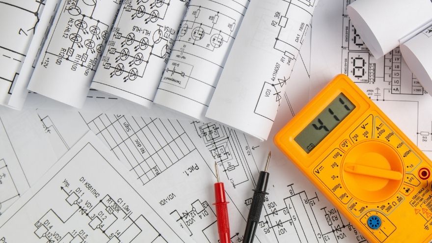
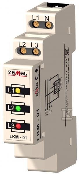
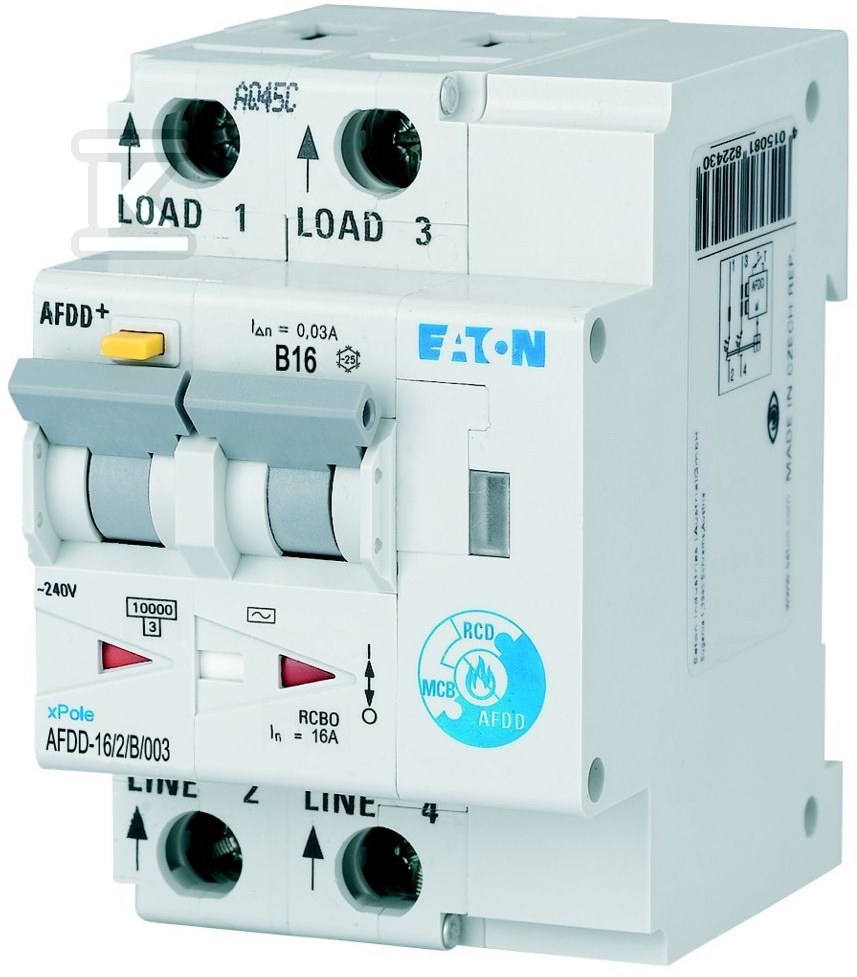
The ability to read electrical diagrams is essential in the work of every person professionally involved in electrical installations. You can say that an electrical diagram is a kind of map containing important tips that allow you to safely "move" in the electrical circuit system. You need to know how to analyze electrical diagrams precisely, especially when you deal with the modernization and servicing of electrical installations on a daily basis. Review a few useful tips and your ability to read electrical diagrams will definitely be at a higher level.

Check the cable and wires at the Onninen wholesaler
Basic Types of Wiring Diagrams
 Electrical diagrams are advanced technical drawings that show the exact structure of an electrical system. They are used not only in large domestic and industrial installations, but also in devices such as advanced electrical equipment or modular equipment .
When you know how to read electrical diagrams, you can freely upgrade installations and connect new equipment in accordance with technical guidelines.
We divide diagrams into four types of documentation, namely:
- Basic – here the most popular are electrical maps, which are used to mark the construction of the entire installation. On such a diagram you will find the exact places where specific devices will be present and their symbols affecting the functions of the electrical installation.
- Explanatory – such diagrams take over the function of a legend when designing integrated circuits and advanced electrical installations. The ability to read electrical diagrams in this form is a must for every installer. Thanks to this, even complex installations used, for example, in industrial control systems will be easier to repair and maintain.
- Executive – on such diagrams you will find data on where the internal and external connections in the system are located, and you will also check the connection diagrams of additional elements, e.g. switches and relays.
- Plans – this is the last group of electrical diagrams, for which basic electrical knowledge is enough to read. Plans are useful, for example, during renovation work, to know where the diagram shows the wires in the walls.
If your daily work involves electrical engineering and complex electrical systems, you need to know how to work with electrical diagrams and how to quickly find important information on them.
What is the function of the electrical components in the diagram?
On electrical diagrams you will find designations of various elements such as cables and wires , coils, capacitors, power sources, resistors, relays, light bulbs and many others. The individual elements that almost every electrical diagram contains are:
-
 Wire lines – here we distinguish between power wires (solid line) and PE (dashed line). All installation wires should be included in the electrical documentation.
 - Nodes and connections – these indicate how individual component ends are connected in the electrical installation. The marking of connectors is essential – these are always the places where wires are connected in the entire installation.
- Switches – symbolized as a dashed line cutting through an electrical circuit.
- Relays – elements that open or close an electrical circuit.
- Contactors – indicate the places where circuits are connected in industrial installations, i.e. where automation comes into play.
- Fuses – perform an essential protective function in electrical installations and are marked as a dashed line.
The example diagram may also include symbols for light-emitting diodes, rectifiers, batteries in the circuit, capacitors, photoresistors or even potentiometers. Practically all elements important from the point of view of the operation of the installation or electrical devices should be included in the diagram already at the design stage.
If you want to know all the symbols, line functions and markings of automation in circuits, be sure to look into the EN60617 and EN61346-2 standards. In the documentation you will find the rules for marking and reading diagrams with specific symbols.
As an expert, you should know what the intersection of electrical circuits looks like. You also need to be able to read documentation and draw diagrams (even simple ones), which makes it easier to make upgrades to existing systems.
How to learn to draw electronic diagrams?
 The basis for learning how to draw electronic diagrams is the ability to create a technical drawing. The rules are simple. When you can create technical drawings, you will be able to easily cope with creating an electrical diagram, even if you are dealing with a complicated device or installation.
Start learning how to draw diagrams by:
- familiarize yourself with the applicable PNE and IEC electrical standards,
- operating programs designed for electricians, e.g. for designing industrial automation and analyzing created projects,
- recognition of symbols used in electrical diagrams.
When you understand the functions of using specific materials in electrical installations and review the most popular combinations of symbols in documentation, you will be able to improve your reading and creating diagrams more quickly.