Certain inconspicuous devices play an extremely important role and significantly affect safety. These include power indicators. Thanks to them, you can check the presence of voltage on individual phases. Zamel power indicators are definitely worth attention. Find out more about them!

Check Zamel power indicators at the Onninen wholesaler
Zamel power indicators - energy-saving operation, safety and reliable operation
 Zamel power indicators have a modern look and a reliable, energy-saving design. Thanks to them, you can effectively monitor the voltage in single- and three-phase networks. The devices indicate the correct voltage relative to the neutral potential. Importantly, signaling is carried out using LED diodes. They are marked L1, L2 and L3. It is also worth knowing that power indicators are available in various colors such as red, green, yellow and mixed. Zamel brand products use optical signaling of the presence of voltage. At the same time, they are easy to adapt to unusual applications. They are used for automation and control. The indicator structure includes connection terminals:
- L1 - screw terminal which is used to apply the supply voltage in the form of the first phase potential.
- L2 - screw terminal used to apply the supply voltage in the form of the potential of the second phase L2.
- L3 - screw terminal used to apply the supply voltage in the form of the third phase potential L3.
- N - screw terminal used to apply the potential of the neutral wire N.
Connection diagram of the Zamel 3-phase LKM-01-10 power indicator
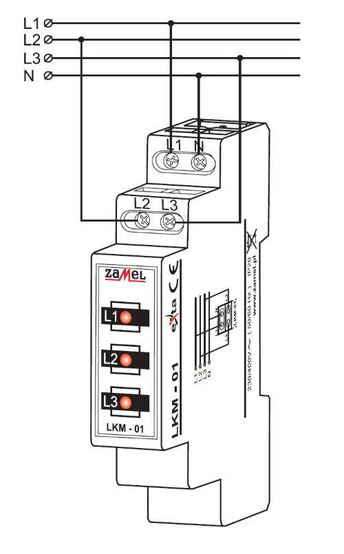 First, disconnect the power supply circuit with a fuse, overcurrent switch or isolation switch. In the next step, for safety reasons, check the voltage on the power cables. If there is no voltage in them, you can proceed to install the device. The TH35 rail is used for this purpose. You need to connect the wires to the terminals. Remember here that this must be done in accordance with the connection diagram. Only then can the power circuit be reconnected. The presence of mains voltage on a given phase wire is signaled by the lighting of the appropriate LED. Similarly, if there is no mains voltage, the LED will not light. Remember one more important thing: for the device to work properly, you must connect the neutral wire.
Connecting the LKM-01-10 Power Indicator
 First, disconnect the power supply circuit with a fuse, overcurrent switch or isolation switch. In the next step, for safety reasons, check the voltage on the power cables. If there is no voltage in them, you can proceed to install the device. The TH35 rail is used for this purpose. You need to connect the wires to the terminals. Remember here that this must be done in accordance with the connection diagram. Only then can the power circuit be reconnected. The presence of mains voltage on a given phase wire is signaled by the lighting of the appropriate LED. Similarly, if there is no mains voltage, the LED will not light. Remember one more important thing: for the device to work properly, you must connect the neutral wire.
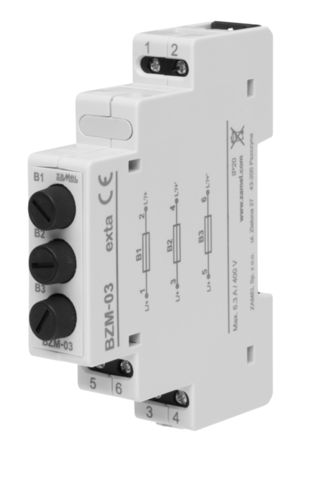
Power indicator protection LKM-01-10, i.e. BZM-03
The LKM-01-40 power indicator can be additionally protected using the BZM-03 module. The device has 3 fuse sockets and protects the indicator against possible effects of device or wiring failure.
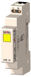
Single-phase power indicator 230V LKM-03-30 yellow exta ZAMEL - connection diagram
Single-phase power indicator 230 V LKM-03-30 yellow extra Zamel is used to signal the voltage in a single-phase network, which is realized using an LED diode. Here you should know that the LED has increased light emission. The manufacturer used a single-module housing. The very high durability of the single-light element is also noteworthy.
It is worth knowing the connection diagram of the single-phase 230V LKM-03-30 yellow extra Zamel power supply indicator . It is also used in automatic control systems to signal events related to the presence of phase potential. The device has N and L terminals, where N is the neutral wire and L is used to supply the supply voltage. We mount them on the TH35 rail. Spring clamps will come in handy. After installation, it takes up one module. We apply the phase potential to the terminal marked L, and the neutral potential to the terminal marked N. After applying the power supply, the LED turns on and lights up continuously. The system is now ready for operation. After applying the supply voltage, the LED turns on and glows continuously. If there is a voltage failure, the diode turns off.
Zamel power indicators available from the Onninen wholesaler
Noteworthy is the 230V/400V LED LKM-01-40 power indicator . Thanks to him 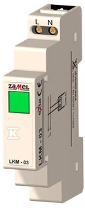 you can not only quickly but also easily check the power status. It is mounted on a DIN rail. With this device you can detect potential problems with power outages. This reduces the risk for devices connected to the network.
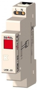
The 230V LED power indicator LKM-03-10 may also be a good choice. It is used to signal voltage in a single-phase network. Its diode has increased light emission. This device will work even in difficult conditions. It has a housing protection rating of IP20. It is also worth paying attention to the rated frequency, which is 50/60 Hz. This power indicator works perfectly in temperatures ranging from minus 20 to 45 degrees Celsius.
There is also a 230V green LED power indicator LKM-03-20 to choose from. In this case, the LED lights up green. Like the previous device, it is also used to signal voltage in a single-phase network. It is mounted on a TH35 rail. The rated supply voltage of this device is 230V.
