As the name suggests, relief and relief valves are used to release liquid from the circuit when its excess causes a dangerous increase in pressure, threatening failure and uncontrolled flooding. But is this their only role? In our guide, we present the principles of their use and advise how to calibrate them properly. We invite you!

What is the relief and relief valve used for?
The purpose of the relief valve is to maintain the operating point of the circulation pump as close to the nominal value . If a relief/differential valve is not installed, pressure losses in the system increase when the flow rate decreases due to partial closure of the two-way valves. A relief and relief valve (also called a relief and differential valve) with a setting equal to the required pump lifting height in the installation allows limiting the pressure increase at the flow rate ΔG through the valve. This operation is ensured regardless of the number of valves closed in the installation. In fact, once the setpoint is set, the bleed pressure value is constant depending on the flow change. A correctly selected valve must guarantee sufficient flow through the bypass to maintain the pump's nominal operating point under all installation operating conditions , for example when thermostatic valves are closed.
Such a valve therefore serves not only as a "fuse" of the installation, but also as a regulator of its correct operation. As the efficiency of the circulation pump decreases over time, the linear resistance decreases and the differential pressure in the installation increases. The valve opens to the set pressure, maintaining the pump's lifting height at an appropriate, constant level. However, for this to happen, it must be installed in the right place and adjusted correctly. It's a bit like a fuse in an electrical installation - if we use, for example, a 25-ampere one, when in fact a 10-ampere one is needed, it will not react properly even when the overloaded socket starts to melt and burn. So how do you properly set up a relief valve? More on this in a moment, let's first deal with the issue of assembly.
Relief and relief valve: where to install?
The relief and relief valve can be installed in any position, just follow the flow direction indicated by the arrow on the valve body. In installations with traditional boilers, the valve is installed at the end of the installation, between the supply and return, which allows pressure control and ensures minimum flow through the heat source. In installations with gas boilers, it is recommended to install a valve after the pump system , which allows for a higher ΔT (temperature change) in the installation, with a lower return temperature, which has a positive effect on the operation of the entire system.
Check out the offer of safety valves now
Relief and relief valve – setting
To adjust the valve, set the knob to the desired value marked on the scale at which the bypass opens . It is worth remembering, however, that manufacturers use different methods of scaling valves - some more directly, according to the pressure value, while others use units of m words (meters of water column). Either way, the valve works on a purely mechanical principle: the knob exerts pressure on a spring that holds the closing element. The more compressed the spring, the greater the force with which the closing element is pressed, and therefore the higher the pressure at which the flow opens.
To quickly adjust the bypass valve, you can use the practical step-by-step procedure. It is as follows: the installation must be running, the control valves must be fully open and the bypass valve (overflow valve) must be set to the maximum value. Close approximately 30% of the thermostatic valves and gradually open the valve using the adjustment knob. You then need to use a thermometer or simply your hand to check that hot water is flowing into the bypass circuit. As soon as you notice an increase in temperature, reopen the thermostatic valves and check whether hot water has stopped flowing into the bypass. Finally, simply lock the knob (e.g. by tightening the locking screw, but solutions in this regard vary depending on the valve manufacturer).
Relief and relief valves are second-class master products. Many users of heating installations may not even be aware of their existence or know how they work , but - paradoxically - this is the best proof of their effectiveness. It is worth approaching them more consciously, because a lot depends on their efficiency and correct setting. Traditionally, at the end, we invite you to review the most recommended models that can be purchased at the Onninen wholesaler.
Overview of products in the Onninen offer
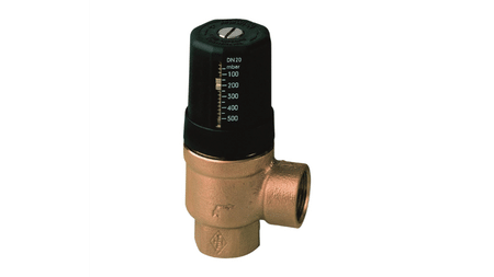
IMI TA Hydrolux DN20 relief and relief valve
 Hydrolux relief valve DN20
- body material: bronze;
- nominal inside diameter: 3/4 inch (20);
- material grade: zinc-free bronze (90/10);
- connection 1: gas conical internal thread (BSPT);
- connection 2: gas conical internal thread (BSPT);
Onnline Pro 15-1/65B electronic drinking water circulation pump
Electronic, high-efficiency circulation pump Onnline Pro 15-1/65B :
- effective in the liquid temperature range: +5° C to +95° C;
- efficiency Qmax up to 0.9 m 3 /h, lifting height Hmax up to 1.1 m;
- automatic air bleeding (allows you to effectively remove air from the pump space);
- maximum pressure in the system 10 bar;
- nominal voltage: 230 V 50/60 Hz;
- The set includes a non-return valve and a thermal cover of the water part, as well as a spare gasket
- high efficiency;
Resideo Braukmann D04FM pressure regulator
The Resideo Braukmann D04FM pressure regulator protects water installations against too high input pressure:
- pressure regulators are used in home and industrial installations, protecting them against damage resulting from pressure changes and reducing water consumption;
- even with strong fluctuations in the inlet pressure, the pressure on the outlet side is kept constant;
- by reducing and stabilizing the pressure, flow noises in the entire installation are minimized;
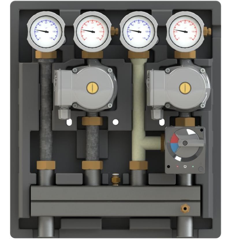
Onnline KOMBIMIX pump group
- type: with mixer;

- built-in pressure gauge: no;
- built-in rotameter: no;
- built-in gas separator: no;
- with pump: yes;
- with plate heat exchanger: no;
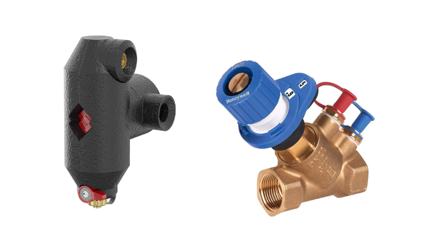
Flamcovent Clean Smart air and dirt separator
Flamco Meibes Flamcovent Clean Smart air and dirt separator :
- nominal inside diameter: 1 inch (25);
- model: horizontal/vertical;
- with drain valve: yes;
- device pressure class: PN 10;
Danfoss MTCV thermostatic valve for domestic hot water
Danfoss MTCV multifunctional thermostatic hot water valve for domestic hot water with the option of expansion to a version with a thermometer or thermal disinfection module:
- connection 1: female gas cylindrical thread (BSPP);
- nominal internal diameter of connection 1: DN 15;
- nominal internal diameter of connection 2: DN 15;
- housing material: brass;
- connection 2: female gas cylindrical thread (BSPP).
