What are you looking for?
Laying fiber optic cables
Laying fiber optic cables has a significant impact on maintaining optimal attenuation parameters of transmitted signals. Single-mode optical fibers are composed of e.g. 12 or 96 cores (fibers). Modes are the term for different light streams propagating at different angles in a fiber optic channel. In a single-mode cable there is only one such beam, which means that there is no dispersion, which results in, among others: the range of such connections is increased.
The maximum bending radius of the cable is the bending radius of each internal fiber. Typically, the bending radius of the cable is 20 times the cable diameter. Therefore, for single-mode cables with fibers in the G.657A2 standard, the maximum bending radius is 7.5 mm, for G.657A1 10 mm, and for G.652D 30 mm.
For FTTH installations directly in residential buildings, it is recommended to use fibers with the largest possible bending radius (G.657A, G.657B), which will significantly facilitate cable laying and reduce the increase in attenuation in the places of cable bends. Before laying fiber optic cables, you should properly plan their route and the amount of stress acting on the cables. The stresses depend on the cable route and are determined by specific mathematical formulas. The stresses are influenced by, among others: the tensile stress at the beginning and end of the section, the length of the cable, the coefficient of friction between the cable and the duct or guide, the mass of one meter of cable, the angle of inclination and the turning angle.
When laying cables, never exceed the permissible maximum tensile force, which is given in the data sheet provided by the manufacturer. If the value of the tensile force exceeds the permissible value, the method of laying the cable should be changed and, for example, the figure-eight or blowing method should be used. Cables should be laid with appropriate reserves - several or even a dozen or so meters, depending on the specific nature of the implementation. When choosing a fiber optic cable, it is worth choosing a fiber optic cable with a larger number of fibers than needed during the works. Detecting damage to a fiber optic cable is much more difficult than in the case of twisted pair or coaxial cables because it requires the installer to have a reflectometer. After laying the cable, make sure that it is free from any tensile stresses (except for suspension cables adapted to such working conditions).
Installing fiber optic cables
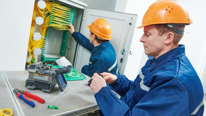
STEP 1. Preparation for splicing fibers
When preparing to install fiber optic cables, after laying them, you must choose the method of connecting the fibers. One of the simplest is to use appropriate trays, distribution boxes or fiber optic boxes at the ends of the cables. They allow you to properly lay the fiber optic cable and reduce the risk of accidental damage at the end of the link. Trays are most often used to complement an existing cabinet, distribution boxes are selected for 19" systems, and boxes are ideal for smaller installations and at the ends of branched lines.
STEP 2. Stripping the insulation from optical fibers
Stripping fiber optic insulation can be done using ordinary cutters, knives or strippers. However, during this stage you should be especially careful and not break the coating or pull the cable. Loads cannot be transferred to isolated optical fibers.
IMPORTANT! When the sheath is exposed, the anti-moisture gel may leak from the external cable. Before placing the fiber in the can, this gel must be cleaned with alcohol. In the case of cables reinforced with aramid fibers, it is necessary to remove these fibers - preferably using Kevlar shears.
STEP 3. Cleaning and cutting fiber optic cables
The next stage is cleaning and cutting fiber optic cables. This is definitely the most difficult and demanding stage of installation work. First we need to prepare the fiber by stripping the cable to a diameter of 125 µm using a stripper. Thanks to this, we will be able to efficiently connect the cable sections. Then, clean the fiber of any dirt, coating residues or vibration dampening gel. Isopropyl alcohol and lint-free wipes are used for this purpose. The fiber must first be cleaned and then cut. If we do the opposite, we will dirty the cut fiber and make it more difficult to weld it together. Please remember not to press the blade against the fiber too much when cutting the fiber with an optical fiber cutter. This will cause microcracks and clouding of the fiber face. After gently marking the breaking point with the cutter, cut the fiber using internal tension.
See fiber optic cables at the Onninen wholesaler
Fiber optic welding
Although the process of installing fiber optic cables after laying them is not particularly difficult, the most problematic thing for installers (especially beginners) is the welding process, i.e. making connectors and joining optical fibers. Properly prepared fibers can be joined using a welding machine, splices and mechanical connectors. They can also be connected by gluing and polishing the joints.
Option 1: Thermal welding
The thermal welding method involves the use of a special welding machine that produces an electric arc that melts the ends of the optical fibers, connecting them together. Thermal welding ensures a strong, safe and durable connection.
Variant 2: Mechanical welds
Mechanical splices use plastic housings to position optical fibers relative to each other, compensating for unevenness. It is best to place the splices in fiber optic boxes or joints, and before connecting the bundles, it is worth checking the connectors with a visual fault locator. It is necessary to check the length of the cut fiber in relation to the specifications of the welding machine or mechanical splice. Each connection method requires the use of appropriate sections. Failure to comply with the required length of the cut fiber in a given connection method will result in strong attenuation, which will limit or prevent signal transmission.
Measurement of attenuation of the transmission path
After installing the optical fiber, the attenuation of the transmission path should be measured. This measurement will allow you to check whether the optical fiber is working properly and whether it has been installed properly. For this purpose, a meter and a constant power light source are used. Optical converters and switches will not provide a stable light source at the output, therefore they should not be used to measure the attenuation of the optical path. The measurement of track attenuation should be performed for the transmission window in which optical devices will be operated. In addition, measuring the attenuation of the transmission path will allow you to determine whether an optical attenuator should be used in the transmission window, which will limit too much power on receiving devices in smaller installations.