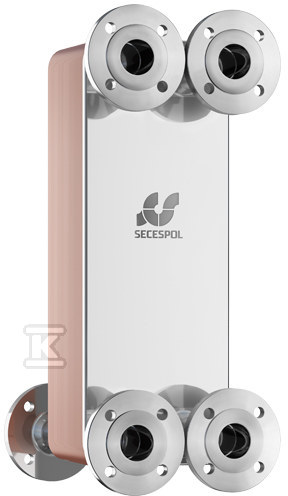
Brazed plate heat exchanger two-pass LC170-130-2S-DN50SS (connections: 6 stainless steel flanges) 0207-1505

Suggested products
TECHNICAL DATA
Sales unit dimensions and weight: 1 pcs
Brazed plate heat exchanger two-pass LC170-130-2S-DN50SS (connections: 6 stainless steel flanges) 0207-1505
Application and Performance in Demanding Conditions
This two-pass plate heat exchanger from the L-line series is a solution designed for installations requiring high performance while maintaining compact dimensions. The device, designated as model LC170-130-2S, is ideally suited for liquid-to-liquid heating and cooling systems. A key element of its construction is the optimized design of flow channels, which enables a high heat transfer coefficient while maintaining low flow resistance. This not only increases the energy efficiency of the entire system but also minimizes the risk of fouling deposition inside the channels, a common issue in standard heat exchangers when operating with lower-quality water.
The two-pass construction (designation "2S") allows the unit to handle more demanding operating parameters than single-pass versions. This is particularly important in circuits where the temperature difference between the primary and secondary media is large or when flows are unstable. This heat exchanger is capable of operating at temperatures up to 230 °C and can withstand a working pressure of up to 30 bar, making it suitable even for industrial installations or high-pressure central heating systems.
Construction, Material, and Resistance
The entire unit is made of stainless steel, ensuring high corrosion resistance and long service life in challenging chemical environments. The plates are permanently joined together via copper brazing in a vacuum furnace. This process ensures not only microscopic tightness of the construction but also a permanent bond of the components, eliminating the risk of leaks resulting from vibrations or cyclic temperature changes. Consequently, the heat exchanger exhibits high resistance to material fatigue caused by sudden pressure surges (hydraulic shocks).
It is worth noting the specific features of this model's connections:
- On both sides (primary and secondary), a nominal diameter of DN 50 has been used.
- The main connections are realized via 6 stainless steel flanges, facilitating installation in piping systems with larger diameters and ensuring a solid mechanical connection.
- External threading has also been applied as a type of main connection and for the secondary circuit, providing flexibility during valve installation.
When planning the installation location, the physical dimensions of the unit must be considered: the total height is 688 mm, and the width is 258 mm. These dimensions allow for precise fitting into available technical spaces without the need for complex structural modifications to cabinets or boiler rooms.
Installation and Operating Conditions
Despite its high thermal power and pressure resistance, the unit features relatively compact dimensions compared to traditional shell-and-tube or plate heat exchangers. This approach allows for space savings in boiler rooms or technical cabinets. The heat exchanger is designed for installation with thermal insulation ("Suitable for insulation: yes"), enabling additional reduction of heat loss or condensation of water vapor on the unit's surface, depending on the direction of media flow.
The installation and potential disassembly process has been simplified by the use of standard steel flanges instead of large-diameter direct threaded connections (which would be heavy and difficult to handle). Installers will appreciate the fact that the brazed construction does not require regular tightening of bolts or gaskets as in the case of gasketed heat exchangers – once installed, the device is "maintenance-free" regarding mechanical tightness throughout its entire service life. However, it is important to maintain appropriate service clearances around the unit due to its height (over 68 cm) and the potential need for access to shut-off valves mounted before the flanges.
CERTIFICATES, APPROVALS, SAFETY, COMPLIANCE AND WARNINGS
Certificate