Petroleum ball valve DN 32 WK2a 1.6 - 4.0 MPa with compensation APA03250040001

Catalog numbers:
- 03250016001
Suggested products
TECHNICAL DATA
Sales unit dimensions and weight: 1 pcs
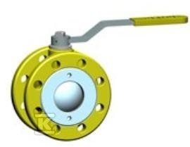
Petroleum ball valve DN 32 WK2a 1.6 - 4.0 MPa with compensation APA03250040001
Application and Characteristics of the Valve
The device with a nominal diameter DN 32, designated as WK2a, is designed for operation in environments requiring high tightness and resistance to high working pressures. Its primary applications include district heating networks, water supply installations, and air conditioning systems where precise shut-off of the medium flow is required. Thanks to its construction adapted for pressures ranging from 1.6 to 4.0 MPa (i.e., 16–40 bar), the valve is suitable for both low-pressure installations and industrial circuits with elevated operating parameters.
It is worth noting the specifics of application concerning petroleum-based media – although the name suggests a broader scope, the provided technical data from the manufacturer indicates use with water and gas (depending on the version), which requires verification of the compatibility of sealing materials with the specific medium prior to installation. The device is standardly equipped with a simple handle for manual operation, facilitating quick opening or closing of the flow. For installations with larger diameters or difficult access, it is possible to replace the standard handle with a worm gear or prepare the body for mounting an electric/hydraulic actuator.
Construction and Key Technical Features
The construction of this ball valve is based on a solid flanged "sandwich" type body, which facilitates its installation between two pipeline flanges without the need for additional external gaskets. Inside, there is a ball made of corrosion-resistant material, which, when rotated by 90 degrees, completely blocks the flow. The key elements ensuring tightness are O-ring seals and a special lower ring, which minimize the risk of leaks even under large pressure fluctuations.
For the installer, dimensional precision and ease of installation are crucial. The flanged connections have mounting holes compliant with the PN-EN 1092-1 standard, where the hole diameter is 18 mm for M16 bolts. The total mounting length (I) is 180 mm, allowing for space savings in tight distribution cabinets or technical ducts. The device weighs approximately 4.3 kg, making it a relatively lightweight component even at DN 32 – this facilitates transport and manual installation without the use of cranes. The valve head has a square profile with a side of 14 mm and a standard F05 control connection, ensuring universality in case of process automation.
The geometric dimensions of the device were designed to maximize functionality while maintaining a compact form: the nominal diameter DN 32 corresponds to a pipeline diameter of 32 mm, and the maximum allowable working pressure reaches 40 bar (4.0 MPa). The distance between the flange faces is 180 mm, which is crucial when planning the mounting space. The outer diameter of the mounting flange is 140 mm, and four holes for M16 bolts are provided for its fastening. The total height of the device, measured from the flange face to the top of the handle, is 173 mm.
Installation and Operating Conditions
Valve installation requires caution due to the presence of sealing elements inside the body. Before tightening the mounting bolts, ensure that the flange contact surfaces are clean and even – irregularities can lead to leaks despite the presence of sealing rings. Tightening should be performed in a cross pattern to avoid asymmetric pressing of the ball and damage to the O-ring seals.
It is worth remembering a few practical aspects of operation:
- The valve is not intended for flow regulation – it should be used only in the fully open or fully closed position. Prolonged holding in an intermediate position may accelerate wear of the ball and seals.
- The control handle should be set parallel to the flow direction for the open state and perpendicular for the closed state – this is a standard visual convention facilitating quickidentification of the installation status during service inspections.
- Due to its application in district heating and water supply networks, the construction material must be resistant to the effects of water and any chemical additives used in these systems (e.g., corrosion inhibitors).
Thanks to its compact "sandwich" construction and high mechanical strength (pressure PS up to 40 bar), this model constitutes a reliable link in the system