Check valve fig. 407A, double-disc, wafer-type, straight DN150PN16 407A150C54

Suggested products
TECHNICAL DATA
Sales unit dimensions and weight: 1 pcs
Check valve fig. 407A, double-disc, wafer-type, straight DN150PN16 407A150C54
Application and Operating Principle in Hydraulic Systems
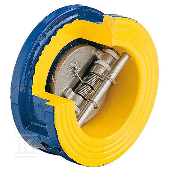
This double-plate wafer check valve (Figure 407A) is designed for automatic prevention of reverse flow in water supply and heating systems. Its primary function is to ensure that the medium – water, glycol, or other neutral fluids – flows in only one direction, thereby protecting pumps and other system components from damage caused by backflow. Thanks to its construction featuring plates made of stainless steel AISI304 and a spring of the same material, the valve responds rapidly to pressure changes, closing even with a slight drop in flow.
It is worth noting that the use of a stainless steel spring enables effective disc closure in any mounting position. This means the installer does not need to worry about the valve's orientation relative to horizontal or vertical axes – the device will operate correctly whether mounted horizontally or vertically. The flow-regulating function with flow limitation ensures that this component not only blocks backflow but also stabilizes system operation.
Robust and Corrosion-Resistant Construction
A key advantage of this model is the combination of body durability with chemical resistance of internal components. The housing is made of gray cast iron EN GJL-250, additionally protected by an epoxy coating. This construction ensures long-term resistance to external corrosion and mechanical stresses resulting from operation at pressures up to 16 bar. The interior of the valve, including the closing plates and pins, is entirely made of stainless steel (AISI304), eliminating the risk of rusting when in contact with water or glycol. The plate seals are made of EPDM rubber, ensuring tightness across a wide temperature range.
Thanks to standard dimensions compliant with EN558-49 and flanged connections PN10/16 (according to EN 1092), installation is simple and quick – it only requires clamping between existing pipeline flanges. The total weight is approximately 8.6 kg, facilitating handling during installation works for DN150 diameter.
Operating Parameters and System Compatibility
The device is suitable for installations operating at a maximum temperature of +100°C (with temporary increases up to +110°C). The flow coefficient Kvs is 467 m³/h, making it appropriate for circuits with medium and high flow rates. The valve is also equipped with measurement ports, facilitating system diagnostics without the need to disassemble the component. Please note that this is a manual (self-acting) construction, not designed for integration with actuators or for expansion into automatic versions – its operation relies solely on the physics of medium flow and spring force.
In practical operation, this model features a nominal diameter DN 150 with a maximum operating pressure of PN 16. The housing is made of gray cast iron EN GJL-250 coated with an epoxy layer, while key internal components such as plates and the spring are made of stainless steel AISI304. The operating temperature range covers values up to +100°C, temporarily up to +110°C. The connection is implemented in the wafer flanged standard (according to EN 558-49), and the flow coefficient Kvs reaches 467 m³/h. Measurement ports are also available, and the device weight is approximately 8.6 kg.
This valve is an ideal choice where reliability is required alongside reduced maintenance costs – the absence of moving parts requiring electric drive minimizes the risk of future mechanical failure.
CERTIFICATES, APPROVALS, SAFETY, COMPLIANCE AND WARNINGS
Declaration of Conformity
Hygienic certificate
The declaration of performance
Attachments