Cable-measurement connector ZK-3/RBL 2x400A+1x160A/2P/F P3024-0007-0L-0P

Suggested products
TECHNICAL DATA
Sales unit dimensions and weight: 1 pcs
Cable-measurement connector ZK-3/RBL 2x400A+1x160A/2P/F P3024-0007-0L-0P
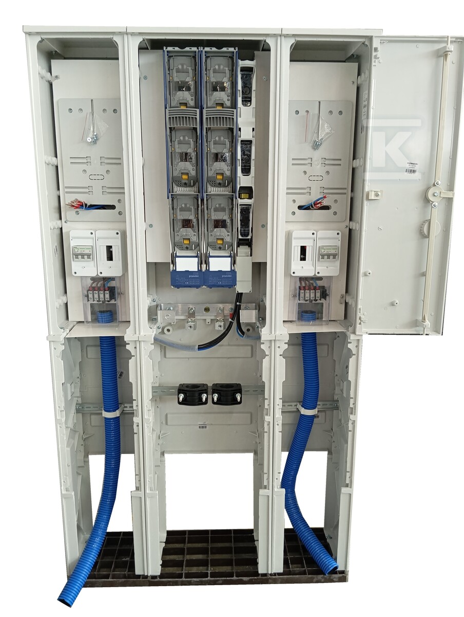
Free-standing cable-measurement connector ZK-3/RBL
The ZK-3/RBL cable-measurement connector is a free-standing device designed according to the PGE 2024 standard. It is used to connect two electrical installations, offering a solution for power distribution and energy measurement.
Construction and enclosure materials
The enclosure is made of steel elements with a minimum thickness of 3,5 mm at the thinnest point, ensuring mechanical strength. The surface is coated with a two-component polyurethane lacquer resistant to UV radiation, guaranteeing resistance to weather conditions and corrosion. The material has a flammability class V0, which means a high level of fire resistance.
Cable compartment equipment
The central part of the device contains busbars made of conductive materials. The system is equipped with two size 2 fuse-switch disconnectors with a rated current of 400A, each terminated with V-type clamps allowing the connection of conductors with different cross-sections. Additionally, a size 00 fuse-switch disconnector with a current of 160A is installed for protecting auxiliary circuits.
Measurement and distribution system
The device features two measurement compartments - left and right, each equipped with a set of measurement elements. Each compartment contains an enclosure adapted for pre-metering protection mounting, a TL-3f meter board, and a pre-payment protection enclosure (FR). Energy distribution is implemented via a 4×35mm² tap-off busbar, ensuring connection to the target installation.
Safety and functionality
The system is equipped with a PEN busbar providing grounding and zeroing of the entire installation. Each measurement compartment has an insulating cover adapted for sealing, allowing access control by authorized services. Additionally, overcurrent circuit breakers and isolating switches are installed, guaranteeing operational safety.
Installation and adaptation
The device is mounted at ground level (580 mm), which facilitates service access. The design allows for the use of different types of roofs - both flat and sloped, adapting to local conditions. There is an option to install an additional cable pocket, expanding the device's functionality with extra space for auxiliary cabling.
CERTIFICATES, APPROVALS, SAFETY, COMPLIANCE AND WARNINGS
Certificate of Conformity
Attachments