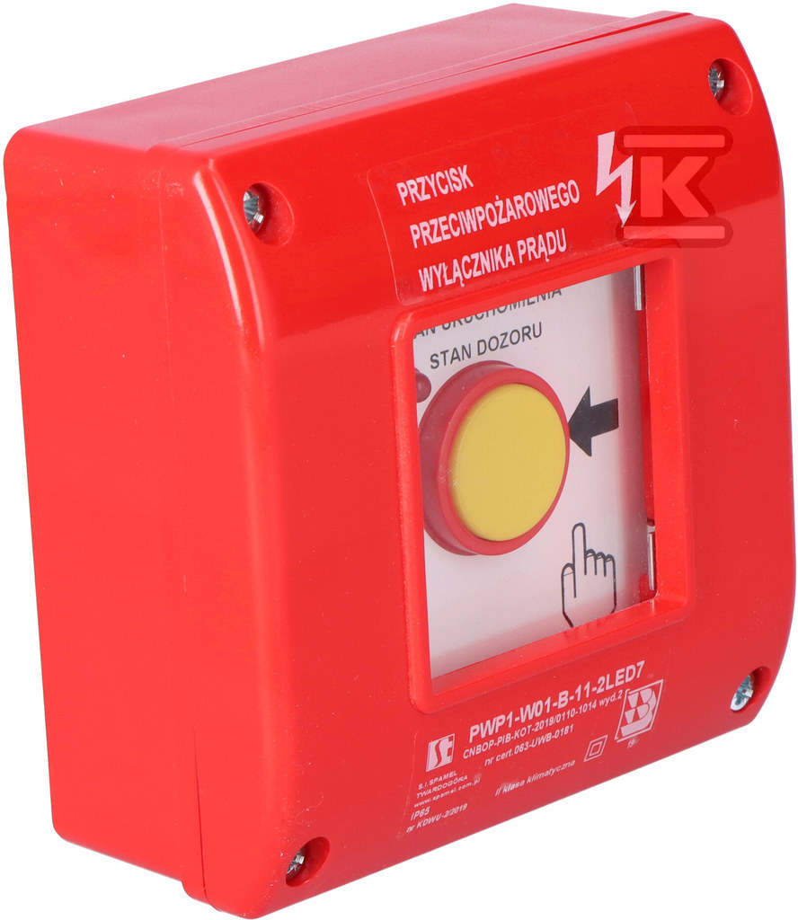
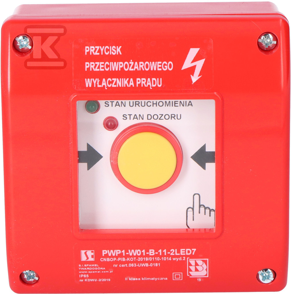
Fire protection (PPOŻ) circuit breaker PWP1-W01-B-11-2LED7. PWP1-W01-B-11-2LED7\.
reviews: 11


Suggested products
TECHNICAL DATA
Sales unit dimensions and weight: 1 pcs
Fire protection (PPOŻ) circuit breaker PWP1-W01-B-11-2LED7. PWP1-W01-B-11-2LED7\.
Fire Emergency Shut-Off Switch – Safety and Installation Protection
This manual push button, functioning as a fire emergency shut-off switch, is crucial for safety in buildings. Its task is to immediately cut off the electrical power supply in the event of a fire, minimizing the risk of electric shock and facilitating rescue operations. The device is particularly important in buildings with a volume exceeding 1000 m³ or containing explosion-hazardous zones.
The switch should be installed near the main building entrance or connection point, with clear signage. It is important that its activation does not automatically re-engage another source of electrical power (except for devices necessary during a fire, such as alarm systems or emergency lighting). The PWP1 manual button can be used as a standard fire emergency shut-off switch after placing an appropriate information plate above it – which is included in the set.
Functionality and Signaling
Model PWP1-W01-B-11-2LED7 is equipped with a dual LED indicator, which informs about the device status:
- Green LED: indicates the operating state (power off).
- Red LED: indicates the monitoring state (power on).
After breaking the glass of the button, the red LED goes out and the green one lights up, confirming the power disconnection. The green LED should be powered independently, preferably before the switch. This ensures that even in the event of a main power failure, information about the power disconnection remains available. The LEDs are terminated with a connection box, which facilitates mounting and integration with the system.
Installation and Requirements
Connecting the switch requires a minimum of 4 wires (depending on the configuration of the LEDs and contacts – detailed information can be found in the technical documentation). Implementation with two LEDs requires a minimum of 6 wires. The device meets the standards PN-EN 60947-5-1 and IEC 60947-5-1 and has a National Technical Assessment CNBOP-PIB No. CNBOP-PIB-KOT-2019/2024/0110-1014 issue 1 and a National Certificate of Conformity No. 063-UWB-0625. The IP65 protection class provides resistance to dust and moisture, allowing installation in various environmental conditions. The connection cables should have a cross-section of 1 to 2.5 mm² (solid core) or 0.75 to 1.5 mm² (stranded). The operating temperature range of the device is from -25°C to +70°C.
CERTIFICATES, APPROVALS, SAFETY, COMPLIANCE AND WARNINGS
The declaration of performance
Attachments
- SPAMEL_PL_Przeciwpozarowy_wylacznik_pradu_PWP1_karta katalogowa
- Oswiadczenie_Spamel_GPSR
- Instrukcja_Spamel_GPSR