Manual start button PWP1 2LED standard PWP1-W01-A-21-2LED7. PWP1-W01-A-21-2LED7\.

Suggested products
TECHNICAL DATA
Sales unit dimensions and weight: 1 pcs
Manual start button PWP1 2LED standard PWP1-W01-A-21-2LED7. PWP1-W01-A-21-2LED7\.
Fire emergency break glass button – safety and rapid response
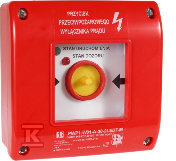
This manual release button PWP1, equipped with a two-color LED indicator, is a key element of fire protection systems. It serves to immediately disconnect the power supply in the event of a hazard, enabling safe evacuation and rescue operations. This button, designed for surface mounting, finds application in public buildings, industrial plants, and anywhere requiring quick and reliable power disconnection in the event of a fire.
Design and functionality
Made of durable plastic (measuring 113 x 113 x 52 mm), the PWP1 button is characterized by high resistance to weather conditions (IP65 protection degree) and mechanical damage. A protective glass pane prevents accidental activation while allowing for quick action in an emergency. Two LEDs – red and green – provide clear visual information about the switch status: the red LED indicates the switch is activated, and the green LED indicates it is deactivated after activation. The green LED informs about the interruption of the power supply. The LEDs are terminated with a connection block, which facilitates integration with the existing electrical system.
Application and compliance with standards
The PWP1 button meets stringent safety standards (PN-EN 60947-5-1, IEC 60947-5-1, IEC 60947-1 and PN-EN 60529:2003) and has a National Technical Assessment CNBOP-PIB-KOT-2019/2024/0110-1014 and a National Certificate of Conformity No. 063-UWB-0625. It can be used as an element of a "Fire emergency power switch", provided that an appropriate information plate is placed above it (a self-adhesive plate is included in the set). The button is available in various contact configurations (NO, NC, NO/NC), allowing it to be adapted to the specific needs of the installation. The rated insulation voltage is 500V and the rated continuous current is 10A. The connection cables should have a cross-section of 1 to 2.5 mm² for solid conductors or 0.75 to 1.5 mm² for stranded conductors. The operating temperature is in the range of -25°C to +70°C.
CERTIFICATES, APPROVALS, SAFETY, COMPLIANCE AND WARNINGS
The declaration of performance
Attachments