Check valve fig. 407A, double-disc, wafer-type - straight DN80PN16 407A080C54

Suggested products
TECHNICAL DATA
Sales unit dimensions and weight: 1 pcs
Check valve fig. 407A, double-disc, wafer-type - straight DN80PN16 407A080C54
Application and Operating Principle in Hydraulic Systems
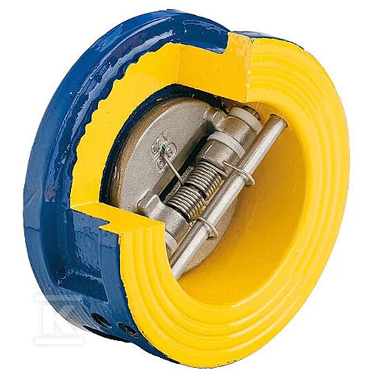
This double-disc wafer check valve (fig. 407A) is designed for automatic prevention of reverse flow in water supply, heating, and glycol-based systems. Thanks to its construction based on a stainless steel spring, the mechanism reacts instantly to changes in flow direction, preventing backflow of the working medium. This is crucial for protecting pumps from damage caused by reverse operation and for maintaining pressure stability within the circuit.
It is worth noting that the applied spring allows the disc to close in any mounting position. There is therefore no need to adapt the valve exclusively to vertical or horizontal installations – the device performs equally well in inclined or even inverted configurations, significantly simplifying design and installation in challenging spatial conditions.
Construction and Resistance to Operating Conditions
The key to the long service life of this model lies in the selection of materials resistant to corrosion and wear. The body is made of grey cast iron (EN GJL-250), additionally protected by an epoxy coating – a standard solution preventing rusting in humid environments. However, the internal components determine reliability: both closing discs, the spring, and the pin are made of stainless steel AISI304 (1.4301). This construction ensures resistance to water, glycol solutions, and other neutral media, even at elevated temperatures.
The device operates within a nominal pressure range of PN 16 (16 bar), and the working medium temperature can reach up to +100°C (with short-term peaks up to 110°C). Seals made of EPDM material ensure tightness across a wide range of thermal conditions. Thanks to standard dimensions compliant with EN558-49, installation is performed using the "sandwich" method between PN 10/16 pipeline flanges, eliminating the need for additional reducers or adapters when replacing older components.
Operating Conditions and Flow Characteristics
For installers, not only the construction but also parameters affecting system hydraulics are important. A valve with a nominal diameter of DN 80 features a flow coefficient Kvs of 95 m³/h, indicating minimal pressure loss at full flow opening. The low weight of the device (approx. 3.6 kg) facilitates transport and installation without the need for heavy lifting equipment.
In practical operation, the device stands out due to its universal mounting capability enabled by the stainless steel spring, allowing operation in any position – from vertical to horizontal and inverted. The grey cast iron body with epoxy coating and internal components made of AISI304 stainless steel guarantee chemical resistance to water and glycol at temperatures up to +100°C (short-term +110°C). The wafer connection compliant with EN 558-49 ensures easy installation between PN 10/16 flanges without additional adapters, while the pressure class PN 16 allows safe operation in systems with working pressure up to 16 bar.
The valve does not feature a drain function or measurement ports, and its expansion to an automated version is not possible – it is a purely manual component designed to protect the circuit against medium backflow. The absence of these additional functions translates into a simpler construction and fewer potential failure points, making it an ideal choice where mechanical reliability and low maintenance costs are the priority.
CERTIFICATES, APPROVALS, SAFETY, COMPLIANCE AND WARNINGS
Declaration of Conformity
Hygienic certificate
The declaration of performance
Attachments