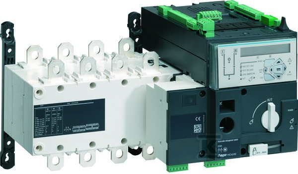
Automatic power switch with measurement and communication, 4P 200 A HIC420E

Suggested products
TECHNICAL DATA
Sales unit dimensions and weight: 1 pcs
Automatic power switch with measurement and communication, 4P 200 A HIC420E
Automatic power switching device with measurement and communication
This device is intended for automatic switching between two power sources in critical installations – e.g., medical facilities, data centers, emergency lighting systems, or industrial plants. It functions as a main disconnect, safety, and maintenance switch, allowing safe isolation of the circuit during service or maintenance. It features a built‑in motorized drive that performs switching without manual intervention – both in case of a network fault and on remote command.
Automatic and remote control
The switch can operate in automatic mode (AUT), where the SZR controller continuously monitors voltage and frequency of both networks – I and II – and decides on switching based on programmed thresholds. In remote mode (via pulse signal or hold on terminals 312–317) switching can be forced from a BMS, SCADA system, or other controller. Communication is supported over RS485 (JBUS/MODBUS) or Ethernet – optional modules are mounted in sockets on the controller panel. Up to 4 I/O modules can be added for programmed extra inputs and outputs – e.g., for generator control or status signalling.
Installation and safety
Mounted permanently in a distribution board. Main terminals are cable lugs – permissible copper conductor cross‑section is from 95 mm² to 120 mm² (for 200 A). The device has no front‑panel IP rating – it must be installed in a closed protective cabinet. It includes a locking mechanism that prevents switching during manual operation, avoiding accidental activation with the cabinet door open. In manual mode (lever released to the handle) the position can be set to I, 0, or II – respectively: network I, off, network II.
LED indicators and diagnostics
The front panel provides full status indication:
green – power present, network I/II availability, active position (I or II)
yellow – manual mode, remote mode, TON/EON/TOF/EOF test
red – controller fault or device unavailable
The LCD display allows programming of network parameters (voltage, frequency), phase sequence, and neutral position – the autoconf function quickly detects these values without manual entry. In case of controller failure the red LED stays lit – reset requires switching to manual mode and then returning to AUT.
Compliance and power
Operates at 380–415 V AC, rated continuous current 200 A. Making capacity at 400 V is 131 kW – sufficient for motors, heaters, or other AC-23 loads. It withstands short‑circuit currents up to 50 kA (Iq) and temporary currents up to 12 kA (Icw). It complies with standards for main disconnects and safety – it does not function as an emergency stop.
CERTIFICATES, APPROVALS, SAFETY, COMPLIANCE AND WARNINGS
Deklaracja zgodności WE