Stationary circuit breaker with sentinel trip unit 55kA 1250A 4P HW1M412FB

Suggested products
TECHNICAL DATA
Sales unit dimensions and weight: 1 pcs
Stationary circuit breaker with sentinel trip unit 55kA 1250A 4P HW1M412FB
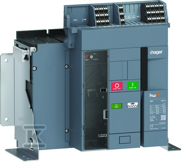
Stationary air circuit breaker with Sentinel trigger
This device is a stationary air circuit breaker rated at 1250 A with 4 poles, designed for permanent installation in low‑voltage switchgear. Its primary function – safe making and breaking of circuits under high currents – is supported by a short‑circuit capacity of 55 kA at 400 V, making it suitable for high‑safety applications such as industrial facilities or data centers.
The built‑in trip indicator allows quick identification of the device status without opening the enclosure – a benefit for both the installer during service and technical personnel during operation. Main connections are designed for busbar mounting, eliminating the need for cables and simplifying integration with busbar type distribution boards.
The device does not have an integrated motor drive, but it supports an optional drive – providing flexibility for automation or remote control. Four auxiliary switching contacts enable status signalling (on/off) in automation or SCADA systems without additional modules.
Ground‑fault protection is not integrated – it must be supplemented with an appropriate release (e.g., an overcurrent release), which is standard practice in modular systems. Likewise, there is no built‑in under‑voltage release – if protection against voltage loss is required, it must be added as an accessory.
The IP2X protection rating indicates that the device lacks a sealed enclosure – typical for stationary breakers mounted in closed switchgear cabinets. It does not require DIN‑rail mounting; its construction allows direct mounting on the panel or frame.
Closing response time is 50 ms – fast enough to avoid over‑voltages during impulsive loads. Mechanical endurance (30 000 cycles) and electrical endurance (8 000 cycles) guarantee long‑term reliability even with frequent operation. Internal resistance of only 25 µΩ minimizes heat losses and reduces the risk of overheating under full load.
Insulation voltage Ui = 1000 V and impulse withstand voltage Uimp = 12 kV ensure safety under network surge conditions. The device complies with IEC 60947‑2 (60947-2) and meets RoHS and REACH requirements.
Construction and installation
Installation is permanent only – it cannot be mounted on a DIN rail or as a pull‑out element. This limitation is intentional: the design is optimized for fixed installation where high short‑circuit capacity and durability are required. Busbar connections allow quick and safe attachment of large‑section conductors without the need to screw numerous cables.
An optional motor drive can be added later – ideal for systems planning future expansion or automation. Auxiliary switching contacts are already built in – simply connect them to a controller or status indicator.
Applications and benefits
For the installer: No DIN‑rail mounting simplifies switchgear design; busbar connections reduce installation time; optional drive allows later upgrades without replacing the whole unit.
For the end user: Trip indicator eliminates the need to open the cabinet for diagnostics; high short‑circuit capacity (55 kA) ensures safety even in extreme fault conditions; low resistance reduces energy costs over the device’s lifetime.
Required accessories: Selection of the appropriate release (e.g., overcurrent), closing coil, or DC power supply depends on the specific automation system – all are available as separate components.
Safety: The device does not have IP44 or IP65 protection – it must be installed in a closed cabinet with an appropriate protection rating.
CERTIFICATES, APPROVALS, SAFETY, COMPLIANCE AND WARNINGS
cert_title_certyfikat_pep_(certyfikat_profilu_ekologicznego_produktu)[eko_label]
Deklaracja zgodności WE