Power switch I-0-II 4P 125A HI451

Suggested products
TECHNICAL DATA
Sales unit dimensions and weight: 1 pcs
Power switch I-0-II 4P 125A HI451
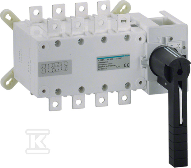
Power switch I-0-II 4P 125A – solution for safe switching of two power sources
The device is used for switching between two low‑voltage sources under load, maintaining physical separation – thus it functions as a safety, maintenance and main disconnect. It has three stable positions: I – 0 – II, allowing complete circuit isolation before service work or power‑source replacement.
Cable clamps accommodate rigid conductors with a cross‑section of 35–50 mm², matching typical conductors in high‑current distribution installations. A long rotary handle enables comfortable and safe operation even when mounted in deep panels, and its black colour provides contrast and readability.
The latching mechanism locks the handle in the “0” position, preventing accidental activation during maintenance – a key feature for installers working in environments requiring compliance with safety standards. The device lacks an emergency stop (NOT-AUS), so it is not intended for rapid shutdown in emergency situations – its purpose is controlled, deliberate switching.
It is permanently mounted in distribution boards – not mounted on a front plate or through holes. There are no auxiliary contacts, so it cannot be connected to control or signaling circuits. It also has no motor drive – everything operates manually.
Compatibility and operating conditions
Operates at voltages up to 690 V AC (rated 380–690 V), covering standard three‑phase systems in industrial and commercial construction. Withstands short‑circuit currents up to 100 kA when used with gl‑gG fuses – a value suitable for the most demanding installations where fault currents are high. The short‑time withstand current is 12 kA for 1 s, confirming resistance to fault impulses.
Rated load at 400 V is 82 kW under AC-23 (motor load) and 63 kW under AC-3 (pumps, fans). This means it can safely switch circuits with motors up to 63–82 kW without risk of contact welding. Insulation is designed for 800 V, and voltage‑impulse withstand reaches 8 kV – ensuring safety even during over‑voltages.
IP00 protection class indicates no protection against touch or foreign objects – the device must be installed in a closed panel. There is no dust or moisture protection on the front – normal for components that are part of a distribution system.
Construction and mounting
Designed as a fixed device, mounted on a rail or panel inside the board. It occupies 8.5 modules (module slots), facilitating precise component layout planning. Dimensions: 251 mm width, 135 mm height, 218 mm depth – critical data for panel size design.
Total power loss at rated current is only 7.6 W, resulting in low heat generation and no need for additional cooling. The tightening torque for the clamping screws is specified at 9–9.9 Nm – this must be observed during installation to avoid damaging the clamps or causing poor contact.
There is no option to add a motor drive or voltage trigger – the device is purely manual and mechanical. Its advantage is simplicity: no electronics = higher reliability and longer service life.
CERTIFICATES, APPROVALS, SAFETY, COMPLIANCE AND WARNINGS
Deklaracja zgodności WE