SPD Surge Protective Device T2 4P 4+0 TN-S network In=20kA Imax=40kA Up≤1.35kV SPE440S

Suggested products
TECHNICAL DATA
Sales unit dimensions and weight: 1 pcs
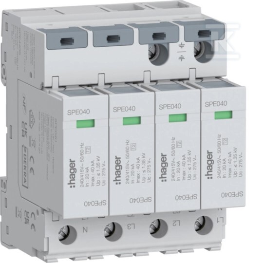
SPD Surge Protective Device T2 4P 4+0 TN-S network In=20kA Imax=40kA Up≤1.35kV SPE440S
Surge protection in TN-S installations
The T2 class surge arrester is designed to protect electrical devices against voltage surges occurring in TN-S networks. The 4-pole 4+0 configuration covers all working conductors (L1, L2, L3) and the neutral conductor (N), protecting loads from phase-to-phase and phase-to-neutral surges.
The device is characterized by a nominal discharge current In = 20 kA (measured at an 8/20 µs impulse according to IEC 61643), allowing it to effectively absorb energy from typical atmospheric and switching surges. The maximum discharge capacity Imax of 40 kA represents the upper limit of the device's capability under extreme conditions - once exceeded, the arrester requires replacement.
The voltage protection level Up ≤ 1.35 kV means that even at maximum surge load, the voltage at the device output will not exceed this value. This is critical information for the protected load - most modern electronics (PLC controllers, inverters, BMS systems) tolerate voltages up to approximately 1.5-2 kV for a very short duration.
The continuous operating voltage Uc = 275 V AC defines the maximum phase voltage of the network at which the arrester can remain connected indefinitely. The nominal voltage range Ue = 240-415 V AC covers standard single-phase and three-phase configurations found in commercial and industrial installations.
Operating parameters and exploitation conditions
The device operates at a frequency of 50-60 Hz, which is the standard for European power grids. The operating temperature range from −40 to +85°C allows for use in both heated rooms and outdoor switchgear or machine rooms - where temperatures can drop significantly in winter or rise in summer.
The maximum recommended overcurrent protection for parallel connection is 315 A. This means that in the circuits supplying the arrester, a fuse or circuit breaker with a rated current no higher than this value must be installed - this is to prevent damage to the arrester itself in the event of an installation fault.
The modular design occupies 4 modules on a DIN TH35 rail, which corresponds to a width of approximately 71 mm. The height (96.6 mm) and depth (71.5 mm) fit within standard dimensions for modular devices mounted in switchgear.
Connection and installation
Screw terminals support conductors:
- flexible (multi-strand) with a cross-section of 1.5-35 mm²
- solid (single-strand) with a cross-section of 1.5-50 mm²
The nominal terminal tightening torque is 3-3.5 Nm. Correct tightening is important both for electrical safety (minimizing connection resistance) and mechanical stability - insufficient torque can lead to wire loosening due to vibrations or temperature changes.
The device is not equipped with a remote signaling contact - operating status information is available only via an optical indicator located on the front of the housing.
Environmental compliance and standards
The arrester meets the T2 requirement class according to IEC 61643, confirming its ability to protect against surges generated by atmospheric discharges and switching operations in the power grid.
The product is:
- halogen-free - the housing and structural elements do not contain halogens (crucial for smoke emissions in case of fire),
- REACH compliant and free from SVHC substances - it does not contain substances listed as particularly hazardous,
- RoHS compliant - elimination of substances such as lead or mercury.
Technical documentation includes the declaration of conformity and the product data sheet available on the manufacturer's website.
CERTIFICATES, APPROVALS, SAFETY, COMPLIANCE AND WARNINGS
Declaration of Conformity