Three-phase busbar blocks B3.1/5-PKZ0 044948


Suggested products
TECHNICAL DATA
Sales unit dimensions and weight: 1 pcs
Three-phase busbar blocks B3.1/5-PKZ0 044948
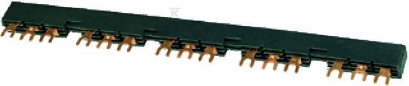
Three-phase busbar block for powering motor starter protectors
The B3.1/5-PKZ0 three-phase busbar block is an insulated switchgear component designed to power up to five PKZM0 motor starter protectors. The device provides a rated continuous current of 63A at a maximum operating voltage of 690V.
Design and technical parameters
The busbars are manufactured in a three-phase configuration with three poles, offering a rated impulse withstand voltage of 6kV. The design, with a length of 264mm and a width of 14.5 DIN modules (54mm pitch), ensures compact density within the switchgear. The component features a fork connection, allowing for easy installation of supply cables.
The device operates in temperatures from -25°C to +55°C, maintaining full functionality in harsh industrial conditions. The black insulation color provides additional protection against mechanical damage. The solution meets overvoltage category III requirements with pollution degree 3.
Application and user benefits
The block enables the powering of five PKZM0 devices from a single connection point, significantly simplifying switchgear installation. The built-in phase failure detection function protects motors from hazardous operating conditions. The design ensures a very high short-circuit breaking capacity: up to 150kA for currents up to 10A and 50kA for the 12-32A range.
The possibility of tool-free connection to DILM7..15 contactors using the PKZM0-XDM12 adapter eliminates the need for additional wiring. The component is compatible with the entire PKZM0/PKZM01/PKZM4 accessory series, including trip units, lateral and front auxiliary contacts, and trip indicators.
Compliance and operating conditions
The solution holds full international certification: CE, CSA Class No. 3211-06, UL File No. E36332, and standards IEC/EN 60947-4-1 and UL 508. The device generates a total heat dissipation of 8.4W, which is 2.8W per pole, allowing for precise thermal calculations of the switchgear.
The component is intended for devices without auxiliary contacts and without a neutral N conductor. Installation requires maintaining appropriate clearances and can be expanded by rotating the installation according to the switchgear design requirements.
CERTIFICATES, APPROVALS, SAFETY, COMPLIANCE AND WARNINGS
Declaration of Conformity
Information about websites