Pressure reducer 6247 3 inch 6247.80.000
Suggested products
TECHNICAL DATA
Sales unit dimensions and weight: 1 pcs
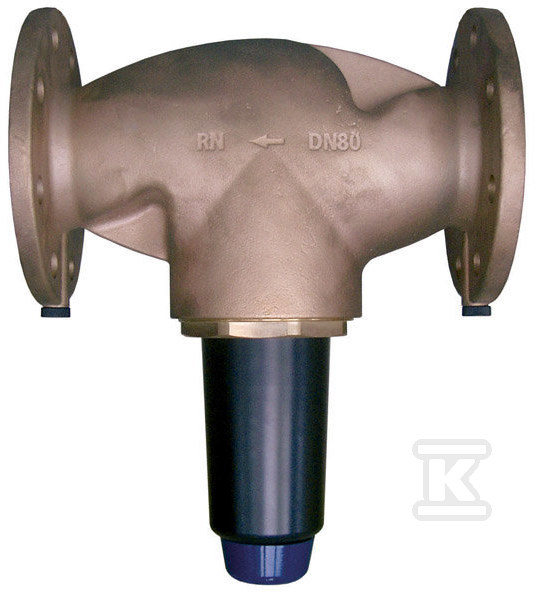
Pressure reducer 6247 3 inch 6247.80.000
Application and Operating Principle in Industrial Installations
A pressure reducer with a nominal diameter DN80 (3 inches) is a device designed for precise pressure regulation in large industrial installations. Its primary function is to reduce the pressure of working media – such as water, compressed air, neutral gases, or non-adhesive fluids – to a level safe for the downstream section of the system. This device is critical where pressure stability at a given flow rate determines the proper operation of the entire system, for example, in industrial water supply networks.
Thanks to the use of a single regulating insert, this model effectively compensates for inlet pressure fluctuations, ensuring constant outlet parameters. It is worth noting the regulation range: the outlet pressure can be set between 1.5 and 6 bar, providing great flexibility when designing installations with diverse requirements. The maximum permissible working pressure on the inlet side is 16 bar, allowing installation even in systems with high flow rates.
Construction and Technical Safeguards
A key structural element of this pressure reducer is the built-in protective screen made of stainless steel. This screen has mesh openings with a diameter of 0.6 mm, effectively preventing mechanical contaminants from entering the regulating mechanism. Such protection extends the device's service life and minimizes the risk of failures caused by blockages. The flanged connections comply with the prEN 1092-3 standard, facilitating installation and ensuring leak-tight joints under demanding operating conditions.
The device features high flow capacity adapted to its size:
- At DN80 diameter, the maximum flow rate is 36 m³/h under standard operation.
- Under conditions requiring higher flow intensity, the flow can reach 61 m³/h.
It should be noted that the medium temperature must not exceed 30°C. This is an important limitation resulting from the internal construction and materials used for the regulating insert. If installation in a higher-temperature environment is planned, it will be necessary to select a different model or implement additional cooling upstream of the reducer.
Selection and Operating Conditions
The selection of the appropriate reducer size (in this case DN80) should always depend on the anticipated maximum flow rate in the installation. An improperly selected component may lead to excessive pressure drops or noise during operation. For comparison of the capabilities of the entire 6247 series, it is worth noting that the smaller DN65 model handles 24 m³/h under standard conditions (over 48 m³/h maximum), while the larger DN100 achieves 56 m³/h and 78 m³/h respectively under maximum load. Such data help precisely match the device to the specific installation requirements without the need for additional flow-supporting accessories.
Installation of the device requires compliance with standards regarding flanged connections and adherence to the flow direction indicated on the reducer body. Due to the specifics of working with gaseous and liquid media under pressure, regular technical inspections are essential to maintain leak-tightness and ensure the proper functioning of the filter screen and the regulating mechanism.
CERTIFICATES, APPROVALS, SAFETY, COMPLIANCE AND WARNINGS
Declaration of Conformity
Information about websites